With the launch of the third generation of Unified Fabric, Cisco’s UCS system has moved well ahead of the simple 2*10GbE interfaces that a single blade can have. It now delivers up to 80GbE to a single blade in a dual 40GbE way. How is that achieved? What are the options?
There are four main parts that you need to understand in order to answer the above question.
– Backplane
– IO Modules
– Blades, the M2 and M3
– Adapters
You will see in the following pictures and text an A-side and a B-side. The data plane is split into two completely separate fabrics (A and B). Each side consists of a Fabric Interconnect (UCS6100/6200) and an IO-Module (2100/2200). And each blade is connected to both the A and B sides of the fabric. This is a full active/active setup. The concept of active/standby does not exist within the Cisco UCS architecture.
Backplane:
Since Cisco started shipping UCS in 2009, the Cisco 5108 chassis uses the same backplane. It is designed to connect 8 blades and 2 IO Modules. The backplane contains 64 10Gb-KR lanes, 32 from IOM-A and 32 from IOM-B.
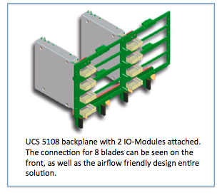
All UCS Chassis sold to date have this backplane which provides a total of 8 10Gb-KR lanes going to each blade slot. This means every chassis sold so far is completely ready to deliver 80Gb of bandwidth to every blade slot.
IO-Modules
The IO Modules are an implementation of the Cisco Fabric Extender (FEX) architecture, where the IO-Module operates as a remote line card to the Fabric Interconnect. The IO-Module has network facing interfaces (NIF) which connect the IOM to the Fabric Interconnect, and host facing interfaces (HIF) which connect the IOM to the adapters on the blades. All interfaces are 10Gb DCE (Data Center Ethernet).
There are three different IOMs, each providing a different number of interfaces.
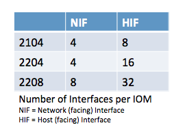
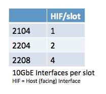
With 8 blade slots in the chassis, the table on the right shows the number of 10Gb interfaces that are delivered to a single blade slot.
Lets complete the picture and look at the total bandwidth going to each blade slot. Each chassis has the A-side and B-side IOM, and each IOM provides the number of interfaces listed in the above table. Because UCS only runs in active/active, that brings the total bandwidth to each blade slot to:

The Blades and Adapters
Hopefully by now you will have understood how the backplane delivers 8 10Gb-KR lanes to each blade slot and that the choice of IO Module determines how many of these are actually used. Now the blades themselves connect to the backplane via a connector that passes the 8 10Gb-KR lanes onto the motherboard.
Depending on the generation of blade (M2 and M3) these 8 10Gb-KR copper traces are distributed amongst the available adapters on the blade.
M2 blade
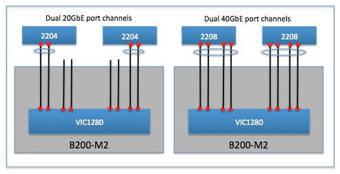
This is the easy one to explain because the M2 blades are designed with a single mezzanine adapter slot. That means all 8 10Gb-KR lanes go to this single adapter. Depending on the adapter that is selected to be placed in the mezzanine slot, the actual number of interfaces available will differ. Every adapter will have an dual interfaces connected to both IOM-A and IOM-B.
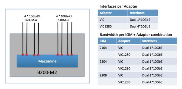
The adapter choice for the M2 blades is either a 2 or 8 interface adapter. Remember the backplane and IOM paragraph, the IOM choice also determines the number of active interfaces on the adapter as can be seen in the above picture and table.
The final piece to be aware of is the fully automatic port-channel creation between the VIC1280 and the 2204/2208. This creates a dual 20GbE or dual 40GbE port-channel with automatic flow distribution across the lanes in the port-channel.
M3 blade
The M3 blades offer both an mLOM slot as well as an extra mezzanine adapter slot. It splits the 8 10Gb-KR lanes it receives from the backplane to both. This means customers can run a redundant pair of IO adapters on the M3 blade if they desire (some RfP’ explicitly ask for physically redundant IO adapters).
The M3 blade splits up the 8 10Gb-KR lanes by delivering 4 to the mLOM and the remaining 4 to the mezzanine slot. Of course these are connected evenly to the IOM-A and IOM-B side. There are also 4 lanes that run on the motherboard between the mezzanine and mLOM.
This means that the mLOM slot receives a total of 8 10Gb-KR lanes, 4 from the backplane and 4 from the mezzanine slot on the blade. This will become relevant when we discuss the Port-Extender options for the M3.
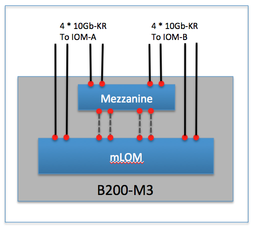
Now that it is clear how the 10Gb-KR lanes are distributed amongst the mLOM and Mezzanine on the blade, lets take a look at how they map to the three possible IO Modules. The mLOM today is always the VIC1240.
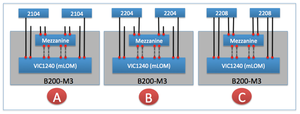
In picture A – with the 2104 as IO Module, it is clear that there is a single 10GbE-KR lane from each IOM that goes to the mLOM VIC1240. The mezzanine slot in this scenario cannot be used for IO functionality as there are no 10Gb-KR lanes that connect it to the IOM.
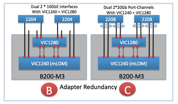
In picture B – with the 2204 as IO Module, there are two 10GbE-KR lanes from each IOM. The mLOM VIC1240 receives a single 10Gb-KR from each IOM. The second 10Gb-KR lane goes to the mezzanine slot. There are three adapter choices for the Mezzanine slot. It is my opinion that the “Port-Extender” will be the most popular choice for this configuration.
In picture C – with the 2208 as IO Module, there are four 10GbE-KR lanes from each IOM. The mLOM VIC1240 will received a dual 10Gb-KR from each IOM. The other two 10Gb-KR lanes go to the mezzanine slot. Again here are three adapter choices for the Mezzanine slot. It is my opinion that here also the “Port-Extender” will be the most popular choice for this configuration.
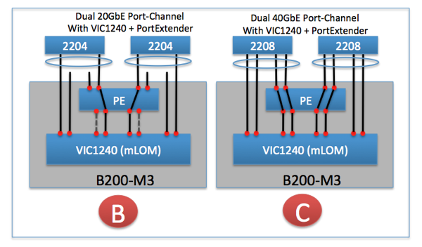
Since I think the Port-Extender will be the most popular mezzanine adapter – lets cover what it is. Simply put, it extends the four 10Gb-KR lanes from the backplane to the mLOM by using the “dotted gray” lanes in the above picture. Look at it as a pass-through module.
If we take both picture B and C and add a Port-Extender into it, lets see what we get. Remember that whenever possible, an automatic port-channel will be created as can be seen in the following picture.
Lets do the same but now use a VIC1280 as a completely separate IO adapter in the Mezzanine slot. This provides full adapter redundancy for the M3 blade for those customers that need that extra level of redundancy. The automatic port-channels are created from both the mLOM VIC1240 as well as the VIC1280 mezzanine adapter.
In Summary
The UCS system can deliver up to 80GbE of bandwidth to each blade in a very effective way, without filling the chassis with a lot of expensive switches. Just two IO-Modules can deliver the 80GbE to each blade. That to my knowledge is a first in the blade-server market and shows the UCS architecture was designed to be flexible and cost effective.
I hope you made it all the way to the end here and have a much better understanding into selecting those UCS components that will give you the optimal bandwidth for your needs.

22 comments
Skip to comment form ↓
Parikshith reddy
March 17, 2012 at 12:57 pm (UTC 2) Link to this comment
Excellent article , I loved it. Very easy to visualize and understand.
Kevin Houston
March 28, 2012 at 11:48 pm (UTC 2) Link to this comment
Good blog post. The new design of the M3 is still a bit confusing to me. What happens if you lose a FEX in the chassis (for whatever reason). Do you lose 1/2 of the 10Gb connections? Also – in your last diagram, “Adapter Redundancy” you show the title of Dual 2 x 10Gb Channels – but isnt’ that 2 x 40Gb Channels (assuming each connection is 10Gb?)
TJ
March 29, 2012 at 7:33 pm (UTC 2) Link to this comment
Kevin,
Thank you for the questions. Let me see if I can clarify both.
On the question of losing 1/2 of the 10Gb connections – let me split that up in two parts because the answer is “it depends”. I say that because it depends on from what point of view you are looking at it.
The FEX (or IO-Modules) connects the chassis to the Fabric Interconnect. If I loose one FEX, obviously the available bandwidth to a chassis is reduced by 1/2 as only the connectivity via the other FEX remains.
From a blade’s adapter point of view, there are the connection to the backplane and FEX, and then there is the connection the adapter provides on the PCI bus which the Operating System will see as physical adapters.
The adapters connection to the backplane and FEX are fixed using the 10G-KR lanes. If you lose a FEX, 1/2 of those connections would obviously no longer be available.
And then you have the other side of the adapter – which provides vNICs towards the Operating System. With UCS you can create a lot of vNICs, and you have the configuration choice to have each vNIC connected to either FEX-A or FEX-B. Normally I see people configure them evenly (e.a. 2 vMotion vNIC’s one via FEX-A and one via FEX-B – but you could configure them to both go through FEX-A if you wanted to).
There is a feature on the Cisco VIC adapter called “fabric failover”. If that is enabled, it doesn’t matter which FEX is configured to the one used by the vNIC because if that FEX is lost, the vNIC will automatically failover to the other FEX and the Operating System will never know about it.
And that is the reason I said “it depends”. Assuming the Fabric Failover feature is enabled, then if you lose a FEX, you would NOT lose any of the connections from the Operating System point of view. You would however lose 1/2 of the available bandwidth.
I hope I was able to articulate that clearly enough.
On the question/comment of the last picture – I can see the wording “dual 2*10G” or “dual 2*20G” is confusing.
The word “dual” is meant to imply one path is going to FEX-A and one path is going to FEX-B (in the picture, the 2204/2208 boxes). Remember that the last picture shows a blade with two separate adapters (1240 + 1280). You cannot create a port-channel that initiates on two physically separate adapters. That is why on the left side of the picture you see “2 * 10Gb”. Because there are 2 individual 10Gb connections, each going to their respective adapter (1240 & 1280) on the blade. That is why I used the term “dual 2 * 10Gb”.
The right side of the picture uses the 2208 FEX which offer more interfaces towards the blade. A single FEX now has 2 10Gb links that go to the 1240 (which will automatically form a port-channel of 20Gb) and 2 other 10Gb links that go to the 1280 and those too will form an automatic port-channel of 20Gb. Hence “dual 2 * 20Gb”.
In the second-to-last picture you see the “dual 40Gb” that you are describing in your question. That is the solution with a single VIC1240 as the adapter (the Port-Extender just patches the connections from the 2208 on towards the VIC1240).
Hope that clears up the confusion.
TJ
Joel Knight
March 31, 2012 at 4:23 pm (UTC 2) Link to this comment
Great article. Thanks for clarifying the number of lanes on the backplane. That’s what made it all click for me.
Hetal Soni
February 28, 2013 at 3:25 am (UTC 2) Link to this comment
Great Article.
1. Looking at last two diagram, It appears to be second from last diagram(PE Adapter) option is better than last diagrm(VIC1280) since it setup 40Gb port channel vs 20gb port channel. Would you please provide pros and cons of these two options. Does PE adapter is physical ?
2. If I have chasis with 8 blades and each is configure with 80GB NIC card– total bandwidth used by all blades is 8×80==640GB, while connection from IO(2208) module to FC is 160GB total. what mechanism will used to distribute this traffic from 640GB to 160Gb?
Thnaks again for sharing this article.
TJ
March 3, 2013 at 11:32 am (UTC 2) Link to this comment
Hi Hetal, thank you for commenting.
Regarding your point 1 – a VIC1240+PE versus a VIC1240+VIC1280 – I would not use the word “better” to select one over the other. From a bandwidth point of view it is a single 40Gb versus dual 20Gb, so equal in terms of absolute bandwidth. The reason to select the VIC1240+VIC1280 is if you have a business need to have redundant adapters. Some customers still state that they do. This way that functionality can be delivered to those customers that require it two totally independent adapters (and are willing to pay for two adapters). The other setup (VIC1240+PE) is a single adapter, where all the Port Expander (PE) does is extend the 10GE traces from the IOM to the VIC1240 (the PE is a small physical card that plugs into the mezzanine card slot)
Regarding point 2 – What you are describing is called over-subscription which every network design has. Servers won’t burst to these numbers (40Gb per fabric) very often (although you can achieve it in a test setup) and certainly not all simultaneously all the time. The mechanism to deal with this is QoS (Quality of Service).
TJ
Chris Welsh
May 15, 2013 at 10:26 pm (UTC 2) Link to this comment
TJ – great article, but one point that often confuses people is missing from your “B” diagrams above.
And that is the case when you have:
a) VIC1240 mLOM installed in a B200-M3
b) 2204 IOMs
c) NO Mez card at all.
From your diagrams it is clear that in this case the B200 will only get 10G in each direction – but you don’t actually make that point. I’m mentioning it here because I have found that many people assume that since each 2204 delivers 20G to each slot, and since the VIC1240 can deliver 20G to each IOM, then they make the false assumption that a VIC1240 will deliver 20G to each 2204 IOM. As I said: your diagrams it is clear that in this case the M3 card will only get 10G in each direction in this case.
TJ
October 31, 2014 at 3:39 pm (UTC 2) Link to this comment
Chris,
First, a big appology for missing your comments. I’m just seeing them now after Pradhakar sent his comments.
You your correct that in that a+b+c combination you mention the blades get only 10G per IOM. Without the Port Expander you are not making use of the 2nd 10G link that is coming from the 2204 IOM.
Thank you for that feedback.
TJ
Hari Rajan
February 17, 2015 at 4:45 pm (UTC 2) Link to this comment
Hi TJ ,
Regarding the 10 Gbps bandwidth availability in mLOM VIC 1240 in B200 M3 is applicable on VIC 1340 mLOM in B200 M4 .
Also could you please let me know the dynamic and static pinning in CISCO UCS also if we have only one IOM how the pinning will be . In a scenario if IOM- A fails immediately how it will be effected on the blades , is there service interrupt will happen ? .
Curious to know this information and looking forward to hear from you soon .
Thanks a lot
Regards
Hari Rajan
TJ
February 18, 2015 at 12:19 am (UTC 2) Link to this comment
Hari,
With the IOM 2204 (or 2208) there is no difference in bandwidth regardless if you are using an mLOM 1240/1340 on a B200-M3/M4. The VIC1340 has some extra features (like VXLAN offload) but from a bandwidth and interface perspective it is identical to the VIC1240.
Most deployments today I believe will be with a port-channel between the IOM and the Fabric Interconnect, in which case pinning of a blade to an IOM uplink port no longer happens. But if you do configure the IOM to not use a port channel, you automatically fall back to pinning.
The pinning “math” is pretty straight forward. List the number of ports you plan on using on the IOM and then write out the blade numbers going from top to bottom. Here are the examples
IOM port: Pinned Blade slot:
1: blade 1, 2, 3, 4, 5, 6, 7, 8
IOM Port: Pinned Blade slot:
1: blade 1, blade 3, blade 5, blade 7
2: blade 2, blade 4, blade 6, blade 8
IOM Port: Pinned Blade Slot:
1: blade 1, blade 5
2: blade 2, blade 6
3: blade 3, blade 7
4: blade 4, blade 8
Failover happens at the adapter level _IF_ you have selected “fabric failover” when you configured the vNIC. It should happen immediately and the host operating system should not see any link-down at all. So the process might take sub-second, from the host OS, it has no knowledge that a failover was triggered and executed.
Hope this answers your question.
TJ
Hari Rajan
February 18, 2015 at 7:26 am (UTC 2) Link to this comment
You are great 🙂 . Glad the way you have answered here !!
It is well clear .. Thanks a lot and I will surely come up with some other questions 🙂
Prabhakar Subhash
October 31, 2014 at 11:51 am (UTC 2) Link to this comment
TJ – Very good article, its awesome!!!
Could you / Chris please explain the last post in detail, i.e IOM 2204 with VIC 1240 mLOM and without Mez Card.
Still I have an assumption of it will have dual 20Gb to each blade server. Since the IOM 2204 will have 2 HIF per slot. But Chris post is correct that it will have only dual 10GB to each server, as I can see the same in my organization environment with this setup.
TJ
October 31, 2014 at 3:43 pm (UTC 2) Link to this comment
Prabhakar,
As Chris rightfully pointed out in his comment, if there is no Port Expander card installed on the blade, in that specific configuration the 2nd 10G connection from the 2204 does go anywhere. You would need the Port Expander card to that 2nd 10G link from the 2204 to actually be passed through to the VIC1240.
So you do have dual 10G in that setup, not dual 20G.
Regards
TJ
Prabhakar Subhash
November 3, 2014 at 10:36 am (UTC 2) Link to this comment
Many thanks TJ, now it got clear!!!
Now I have few questions, Pl provide me the details.
a) In the above scenario, If we use Mez card ( NIC 1240 / 1280) instead of PE, we will get 20GB link from each IOM 2204. In this case how many vNICs / vHBAs can be created? as I seen this usage is for NIC redundancy but on which NIC card the vNICs / vHBAs will get create.
b) How can we check the DCE interface through put? and is there any possibility to check the which VLAN is passing on which DCE interface of a server?
Thanks in Advance!!!
TJ
November 9, 2014 at 1:12 pm (UTC 2) Link to this comment
Prabhakar
a) With two Mezz cards installed (1240 and a 1280 – or now with the newer 1340 and a 1380) you achieve redundancy for a Mezz card failure. Some customers find this important. You still have a total of 80Gb of bandwidth, it is just now split across 2 separate Mezz cards. Now the number of vNICs/vHBAs that can be created doesn’t really matter – it is limited by the capabilities of the OS which is much lower then what the VIC adapters can achieve. So I could tell you it is 128, or 256… the restriction will come from ESXi, Windows or Linux. You create the vNIC’s inside UCSM and you assigned them to one of the Mezz cards. So your policy decides on which Mezz card your vNIC/vHBA is terminated.
b) Your vNIC configuration holds all that information. It shows you which VLAN’s you have assigned to which vNIC. And you can collect throughput numbers (very detailed) on a per vNIC basis in the GUI as well (don’t know top of my mind exactly in which screen).
Regards,
TJ
Prabhakar Subhash
November 20, 2014 at 7:58 pm (UTC 2) Link to this comment
Sorry for the delay… Thanks TJ, its clear now 🙂
Justin
March 23, 2015 at 9:03 pm (UTC 2) Link to this comment
In order to achieve the 40Gb/s on both sides with the 1240/1280 or the 1240/PE combo, do the IOMs have to have all 8 links connected to each FI? Or will a 4-link connection configured as a port channel work?
TJ
March 24, 2015 at 10:19 am (UTC 2) Link to this comment
Justin,
We need to seperate two topics.
If you have an IOM2208 and the 1240/1280 or 1240/PE you will have 40Gb/s of bandwidth available to you between the IOM and the server blade. That is irrespective of the number of uplinks you use on the IOM.
Of course if you want to run 40Gb/s of bandwidth to a server, you would need 40Gb/s of bandwidth from the FI to the IOM as well, otherwise you would no be able to fill the 40Gb/s connection to the server.
So in practical term, you need 4 links (but the minimum you need is 1). You can do 8 links, that doesn’t give you more bandwidth to an individual server, but that does give you more shared bandwidth for the combined 8 servers.
Hope this helps
TJ
fouzia Sultana
April 6, 2015 at 5:49 am (UTC 2) Link to this comment
Awesome explanation. Read so many documents to understand. But this one actually.
Thank you 🙂
mazhar
August 12, 2015 at 5:33 pm (UTC 2) Link to this comment
Good work.
Thank you for your time to write the article
Trent
November 28, 2016 at 6:28 pm (UTC 2) Link to this comment
Great article, thank you TJ!
2 Questions if you don’t mind:
1) When using a 2208, you mentioned that you get 4 HIF/slot. Does the cabling impact that? In other words, if we have a 2208 and we only cable up 4 of the 8 slots, are we still going to getting 4 HIF/slot? Or should we expect numbers similar to that of using a 2204? I’m just curious if it’s strictly the hardware (2208) that impact the HIF, or if it’s a combination of the hardware (2208) and cabling (all 8 ports) in order to achieve 4 HIF/slot.
2) Has the architecture changed at all with B200 M4s and the 1340s and 1380s?
Thank you so much!
-Trent
TJ
November 29, 2016 at 11:57 pm (UTC 2) Link to this comment
Trent, thank you for your question.
The answer is much the same as my response to Justin (March 24, 2015). The links between the IOM to the blades are there, and you have 4 of them. If you want to use all 4, you need hardware on both sides that utilize all 4 (an IOM2208, and on the blade side a VIC+PortExpander). That gives you a total of 40Gbps between the IOM and the blade. This is irrespective of how you do your northbound cabling from the IOM to the Fabric Interconnect. If you use just one cable, you have a total of 10Gbps of bandwidth, even if the blade has 40Gbps available to it. This is no different then deciding how much uplinks the Fabric Interconnect will have to the rest of the network, or how much the first Top-of-Rack switch will have to the Core-switch. The physical connectivity to the blade will be 40Gbps.
On your second question, no it hasn’t changed with the B200M4 and VIC1340/80’s.
Regards
TJ